rSkin – Progress Blog
>> ***NEW Progress Blog***
>> Project Page
>> Instructable
>> Flickr set
>> GitHub Repository
>> YouTube Playlist
Updates
Instructable now published >> http://www.instructables.com/id/rSkin-Open-Source-Robot-Skin/
rSkin featured on blog >> http://revoltlab.com/2012/02/15/robotic-skin/
PPS pressure sensors >> http://www.pressureprofile.com/products.php
Three-dimensional pressure measurement by Alphafit
CNMAT Visit (2.12.2011)
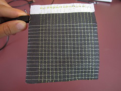
Fabric Multi-Touchpad
– pressure
– location
– 1 layer of fabric, stitches on either side
– rows, columns
– multi-touch
– pressure
Front and back:

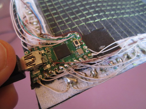
Teensy:
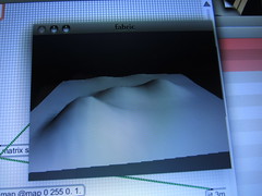
Visualization written in Max/MSP:
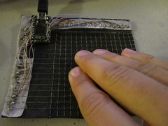
Video
link >> http://youtu.be/ah8FhCbhDZw
Photos of similar setup that does not work well. Adrian says: “My intuition is that the thread can relax and the lack of pretension makes the results noisy and inconsistent.”
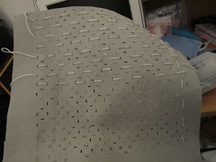
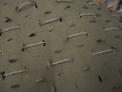
Fabric Touchpad
– pressure
– location
– 3 layers
– 4 connections
– single-touch
– pressure
CNMAT paper >> http://cnmat.berkeley.edu/publication/support_vector_machine_learning_gesture_signal_estimation_piezo_r
Front and back
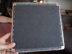
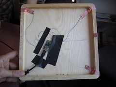
Video
link >> http://youtu.be/gPYyuuL-o7k
Thin, Strong, Solderable Conductive Thread
Eeonyx Visit (2.12.2011)
eeontex >> http://eeonyx.com/eeontex.php
spacer fabric (something like this) >> http://wellcool.en.ec21.com/3D_Spacer_Fabric_3D_Mesh–4072304.html

Some More Photos (20.11.2011)
Controlling the Arm (20.11.2011)
Need a computer running windows or a windows virtual machine (VM).
Download RoboPlus from robotis.com >> http://www.robotis.com/xe/download_en
Quick instructions for motion:
1. Assemble parts as shown below
2. Find which COM port the USB serial device was assigned to (My Computer -> Properties -> Device Manager -> Ports)
3. Start RoboPlus and choose the expert tab, then Dynamixel Wizard
4. Choose the correct com port and then autosearch for dynamixels
Once the dynamixels have been located you’ll be able to individually control their
motion using the Goal Position setting. The servos should be properly limited so they won’t go past reasonable positions, but be careful changing their position all the same.

Goal Positioning
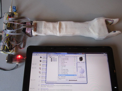
Colour Visualization and Moving Arm

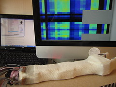
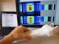
Casting Flesh (18.11.2011)
Smooth-on EcoFlex >> http://www.smooth-on.com/Platinum-Cure-Sili/c1115_1130/index.html

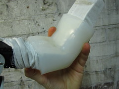
Casting Eco-Flex silicone into mold. I mixed 7oz (3.5A:3.5B) of Eco Flex to fill the mold. It normally takes 4 hours to cure, but because it was so cold in my studio it took twice as long (i left it overnight, so maybe it even took longer).
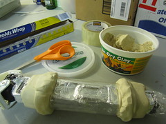
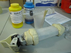
Removing cured silicone from mold. The inside of the cast silicone is shaped by the aluminum foil wrapped around the arm, so there is not so much detail. The cast flesh would fit better if this was done better.
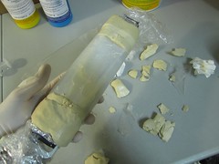
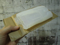
The result is a very squishy layer of silicone that i think will work really well to create a more uniform buffer layer between sensitive skin and hard robot arm. It might also have its downsides, as pressuring in any one point will automatically affect surrounding sensors, as they will be stretched into the indentation of the pressure point.
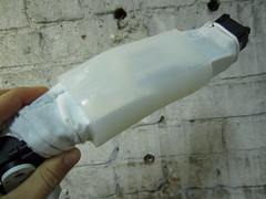
Video
Instructable… (17.11.2011)
I’d like to post an Instructable about the resistive solution to simultaneously sensing location and pressure.
Unpublished link >> http://www.instructables.com/id/EJKTF3WGV490JGK/
Some Ideas for Future Improvements (17.11.2011)
– Better cabling
– Sew hard/soft connections by machine!
– Thicker flesh layer that creates a uniform underlying consistency
– Sew rows/cols with more robust thread
– Sew connections on hand with machine
– Look into other Eeontex fabrics that might yield a different range
– Create a finer grid
– Try to increase the range of sensitivity
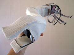
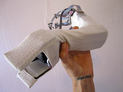
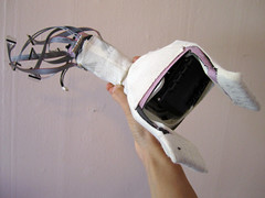
Some Photos (17.11.2011)
Visualization (16+17.11.2011)
The code can all be found in the GitHub repository.
Specifically i am using the following arduino code on the teensy: https://github.com/iandanforth/rSkin/tree/master/teensy/a_rSkin4Multi16
and processing code for the visualization: https://github.com/iandanforth/rSkin/tree/master/vis/p_robotskin_4multi16channel
Hiding what does not exist
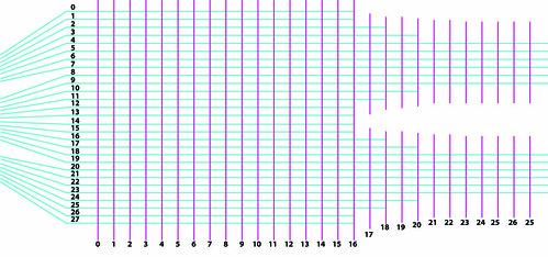
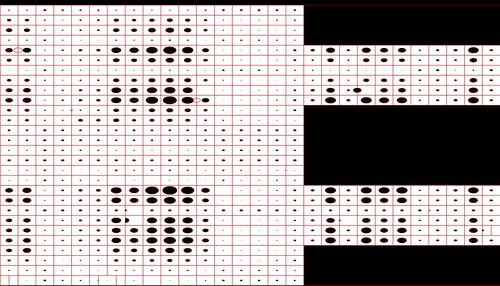
Not all rows and columns intersect, a simple masking of the visualization hides what we should not see, but really i should find a more elegant solution.
Video
Circle Visualization
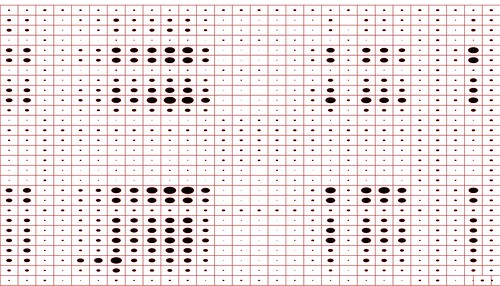
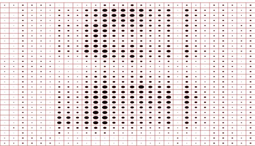
After realizing that the gray-scale visualization doesn’t show up well on video i decided to draw circles instead, their diameter increases with the increase of the sensor value. When i switched from doing the gray-scale to the circle i noticed that the frame-rate improved greatly (though there are still some delay issues, that i have not figured out yet). While the rows and columns are mapped correctly in this visualization, i am not accounting for areas on the hand which the grid does not cover. I have since done so and you can see some screen/shots above. When you watch the video, you might notice how when i am only pressuring the arm in one point, other readings are being affected, this is because it is impossible to pressure the arm in one point without applying counter-pressure elsewhere. And, because the hard arm itself does not have a uniform surface the counter pressure points are often in specific places. Also, pressuring the skin in a point that does not have a hard piece of arm directly behind it, causes the pressure applied to that point to spread to the surrounding area, since that is being stretched.
The following two screen-shots show the relaxed and then squeezed state of the rSkin.
Video
While the auto white-balance effect is better with this visualization, it still has some effect since the overall black/white ratio is changing.
Gray-scale Visualization
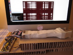
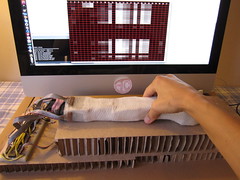
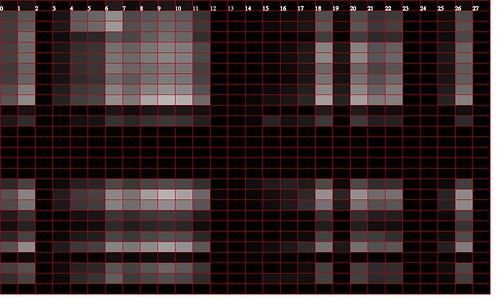
This visualization was very noticeably slower, the larger i made the application’s window size. At a window size of over 1200 width, the visualization was a few seconds behind real-time. I am not quite sure why this would be… but drawing circles (see above) helped solve that issue.
Video
Hard to show on video because my camera constantly adjusts its white balance when the balance of the screen changes. So what you see on video is often very different from what is really showing.
Cleaning Up (16.11.2011)
Re-Mapping Columns Connections
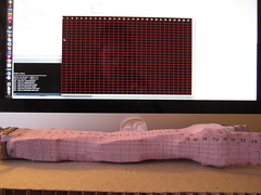
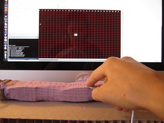
Video
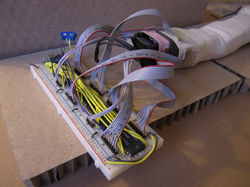
Plugging Flesh and Skin Connections
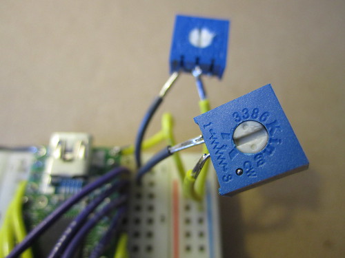
Adjusting Pull-Down Resistors
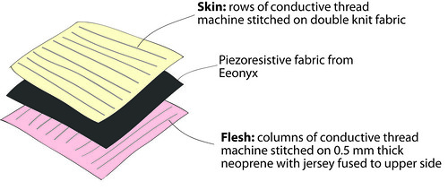
All three layers
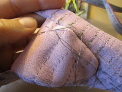
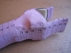
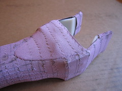
Sewing missing connections between columns on hand

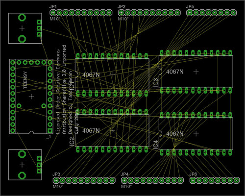
Circuit Diagrams with Eagle (6.11.2011)
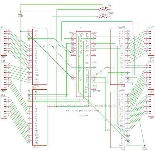
Circuit Schematic
PCB Board Layout
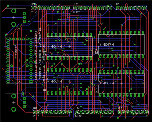
Before autorouting…
Making Life Easier (3.11.2011)
Flat ribbon cable with through-hole inter-lead spacing (0.1 inch, 2.54mm) >> http://search.digikey.com/scripts/DkSearch/dksus.dll?Detail&itemSeq=106924201&uq=634564406054359063
Machine Sewable Hard/Soft Connections
Using fusible interfacing to connect conductive fabric strips to perforated circuit board. Sewing with top conductive thread to fabric breakouts and soldering wires to perfboard.
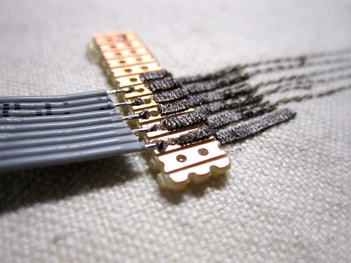
Using zigzag stitch on sewing machine to sew top conductive thread over stripped ribbon cable wires.
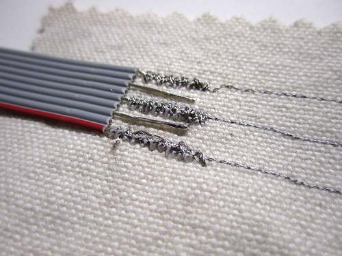
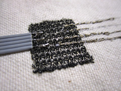
Sewing to Plug and Wear’s knit breadboard fabric (right: with top thread conductive, left: with bottom thread conductive) and then soldering wires to the breadboard traces which are very thin wires.

Debugging (1.11.2011)
After some trial and error experimentation, i found the major mistake in my former code for the robot skin. The bit-shifting code, that is supposed to parse the control pin combinations to read from the individual multiplexer inputs, wasn’t working at all.
A multiplexer is a component which allows you to have more in- or outputs. It works like a gateway, and a 16-channel multiplexer has 4 control pins (ABCD) to which you send various combinations of 1 or 0 to tell it which pin (gate) to connect to.

I tried fixing my bit-shifting code, but also came across some different solutions:
Tom Igoe uses the Arduino bitRead() function >> http://www.tigoe.net/pcomp/code/arduinowiring/540
Buildr uses a two-dimensional array >> http://bildr.org/2011/02/cd74hc4067-arduino/
And others use bit-shifting code >> http://arduino.cc/en/Reference/Bitshift
I ended up implementing a two-dimensional array to store and retrieve the control pin combination values.
Here is are the code examples i used in the following video:
Arduino code >> http://web.media.mit.edu/~plusea/downloads/code/a_rSkin2Multi16.zip
Processing code >> http://web.media.mit.edu/~plusea/downloads/code/p_rSkin_11x11.zip
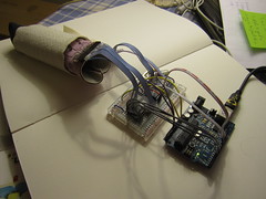
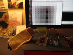
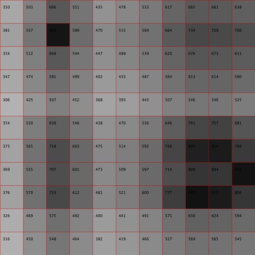
Video
Note that the sensor data from this test setup is quite noisy and too sensitive. This is because the conductive rows and columns are made using strips of conductive fabric, rather than conductive thread as in the final prototype. The video shows: 1) Individual sensor layers disconnected for testing individual (digital) row/column connections. 2) Data stream. 3) Turning the pull-down resistor. 4) Sensor readings with Velostat in between. The Velostat seems to be providing much cleaner values that the Eeontex fabric. This will be something to look into, because in initial (flat) prototypes the piezoresistive stretch fabrics fared better.
Bringing Circuitry, Code and Skin Together (20.10.2011)
Unfortunately the Robot Skin visualization is not working yet, but bellow you will find the current code for both Ardunio (Teensy) and Processing.
Download Arduino >> http://arduino.cc/en/Main/Software
Download Processing >> http://processing.org/download/
Download Arduino code >> http://web.media.mit.edu/~plusea/downloads/code/robotskin_a_4multi16channel.zip
Download Processing code >> http://web.media.mit.edu/~plusea/downloads/code/robotskin_p_4multi16channel.zip
Programming the Teensy using Arduino >> http://www.kobakant.at/DIY/?p=2497
Teensy Loader >> http://www.pjrc.com/teensy/loader.html
Teensyduino library >> http://www.pjrc.com/teensy/teensyduino.html
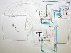
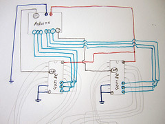
Teensy circuit diagram for Arduino programming:
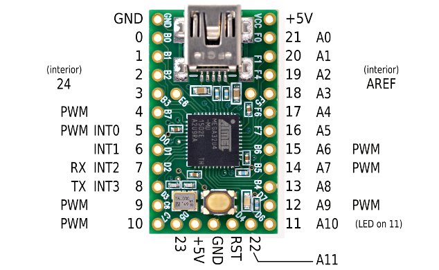
Download stencil file (Adobe Illustrator) >> http://web.media.mit.edu/~plusea/downloads/RobotSkinStencils.ai.zip
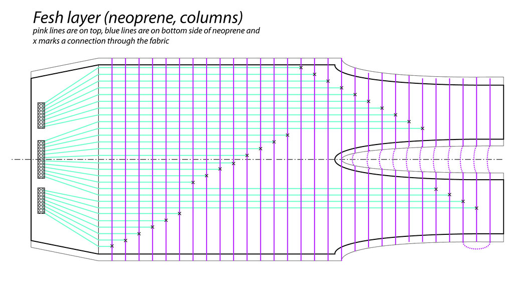
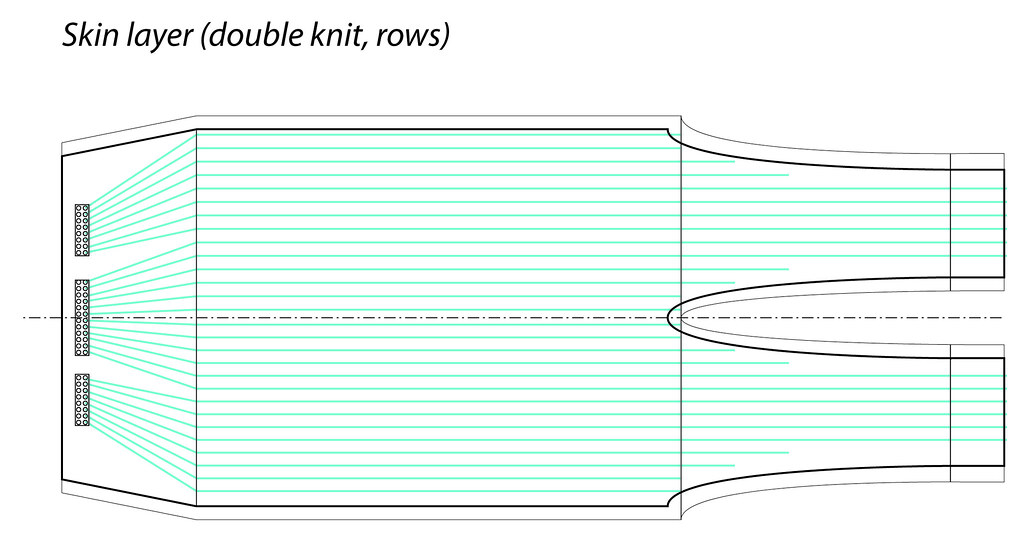
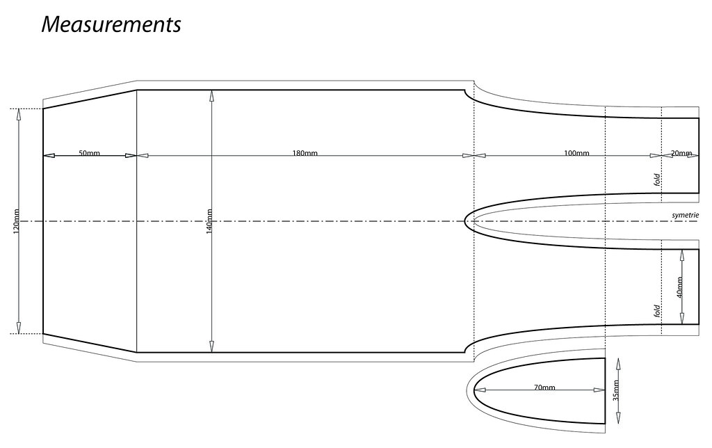
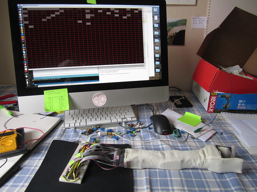
Snap-shot of setup.
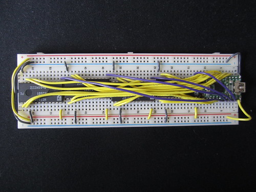
How connections should go:

Breadboarding the circuit.
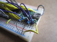
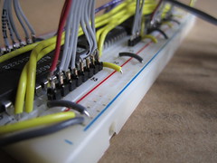
Scaling up the electronics
The Mux (48 inputs) >> http://arduinoshield.net/shields/the-mux-multiplexer-shield-no-more-io-shortages
Mux Shield >> http://www.sparkfun.com/products/9832
Multiplexer shield (plus 16 inputs) >> http://www.thingiverse.com/thing:4128
Parallel to Serial Shifting (plus eight inputs) >> http://www.arduino.cc/en/Tutorial/ShiftIn
Finishing Full Prototype of Skin (18+19.10.2011)
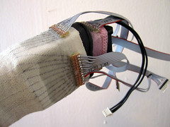
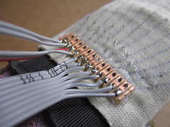
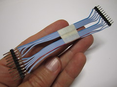
Attaching the ribbon cables, and headers.
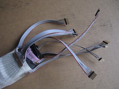
The arm with cables from various angles
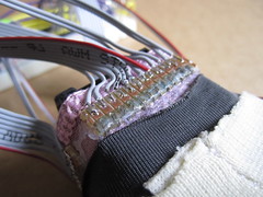
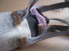
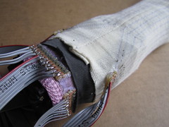
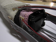
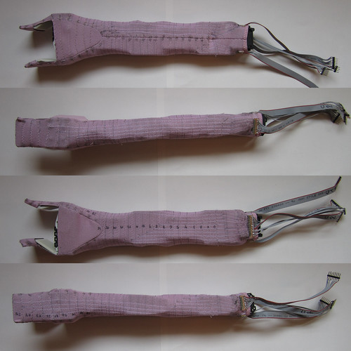
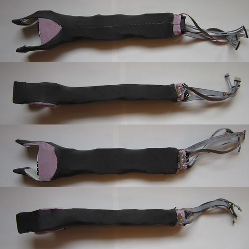
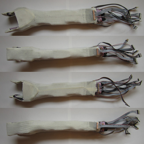
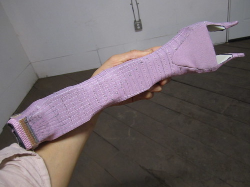
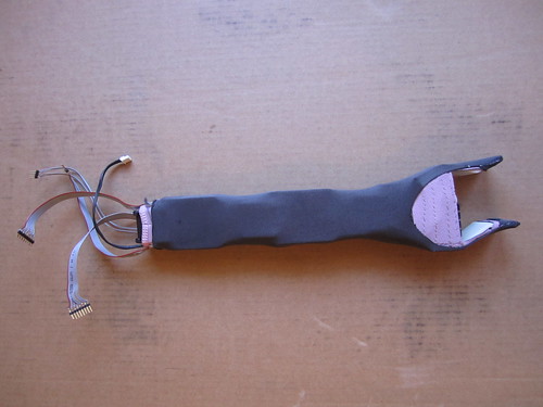
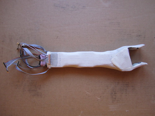
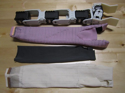
All three layers: Flesh, piezoresistive, skin
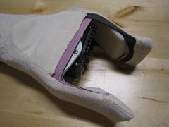
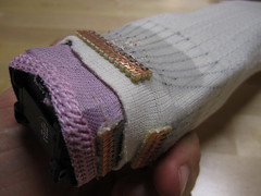
Video
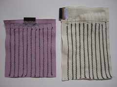
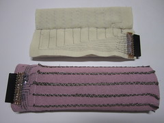
Pink flesh (columns)
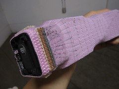
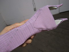

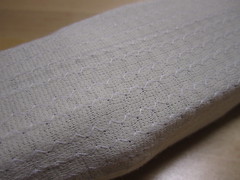
White skin (rows)
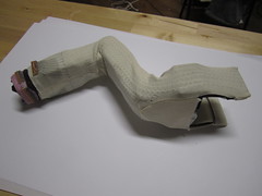
Video of the making-of process
Isolating and protecting hard/soft connections with stretchy fabric glue and Smooth-on Ecoflex. Ecoflex is better.
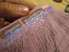
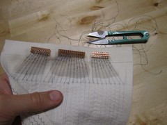
Isolating ends of threads to keep them from fraying.
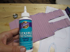
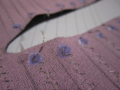
Sewing conductive traces with machine and by hand
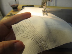
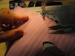
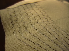
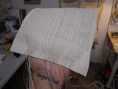
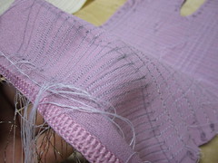
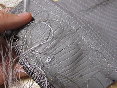
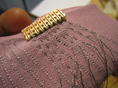
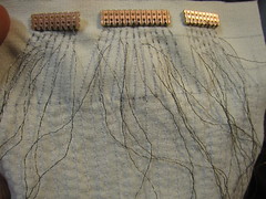
Transferring stencil details.
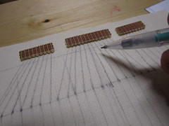
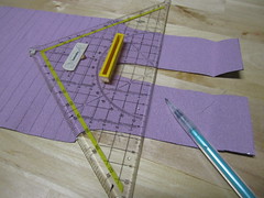
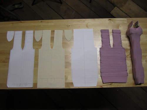
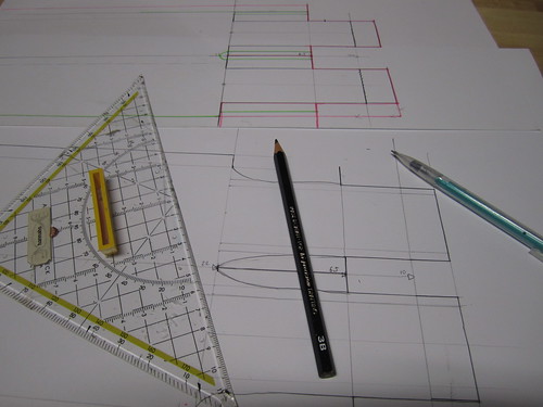
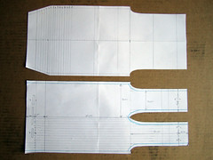
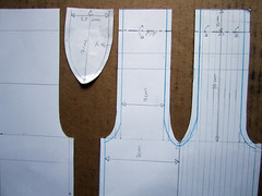
Making stencils and transferring them.
Figuring out the Electronics on Single Joint Prototype (17.10.2011)
Video – coming soon….!
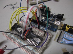
Prototype circuitry, using one 16-channel multiplexer and 11 input pins on Arduino.
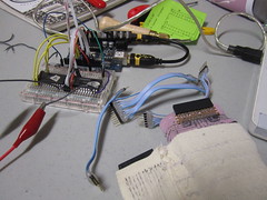
Looks awkward because outer skin layer is not a tight as it should be. 11 pin connector.
Sewn together.
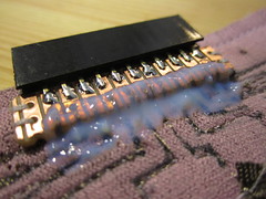
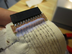
Insulating and protecting with glue.
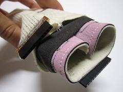
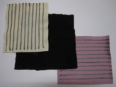
Layers.
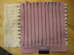
Outer skin layer connections all come back to armpit.
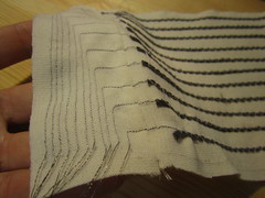
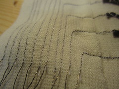
Checking for unwanted connections
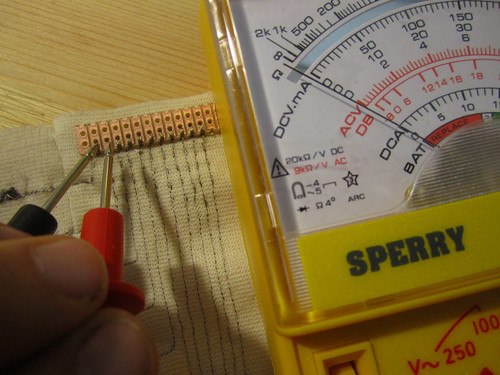
Sewing to perfboard, instead of soldering to wires.
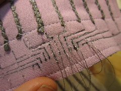
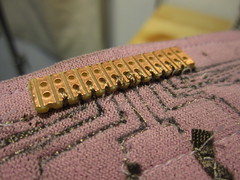
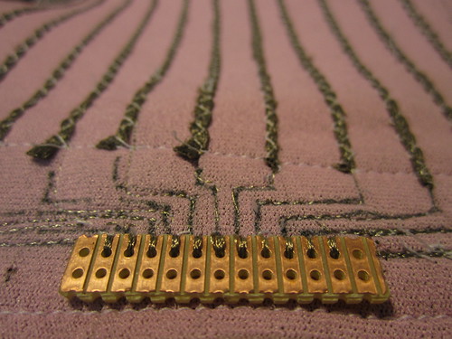
Nope, soldering connections to super thin wires is not going to work. The wires are too fragile and so are the solder connections.
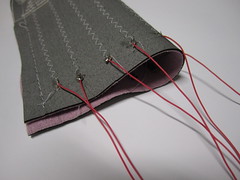
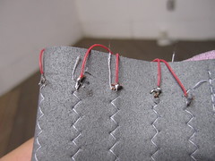
Stretchy traces on neoprene, flesh.
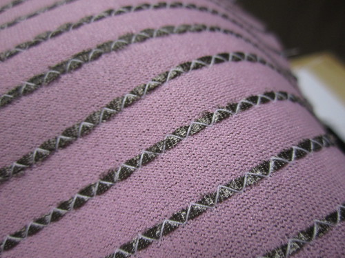
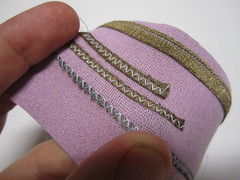
Stretchy ca. 4mm wide conductive traces on double knit skin.
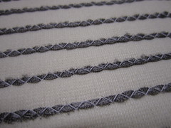

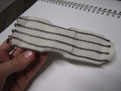
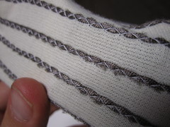
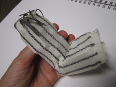
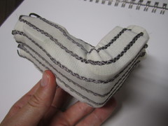
Stretchy trace samples on neoprene and double knit.
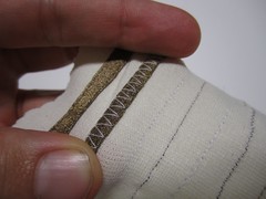
Progress.
Getting the Skin to Fit (15+16.10.2011)
Creasing occurs.
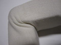
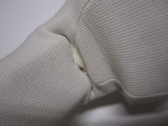
Edited skin, fits much better.
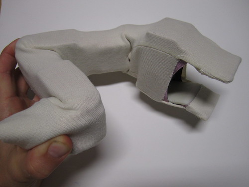
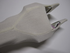
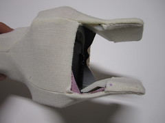
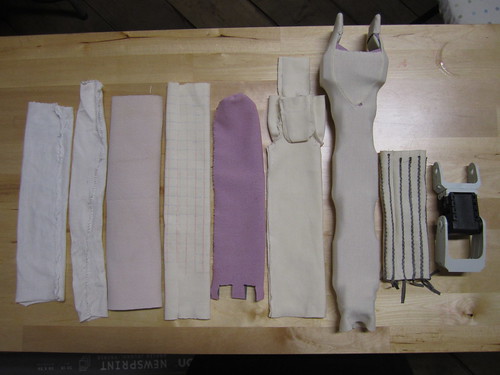
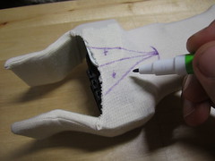
Editing skin to fit better.
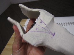
Skin on top of flesh.
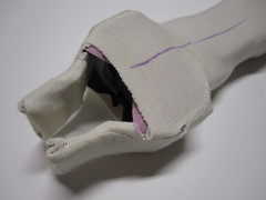
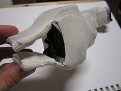
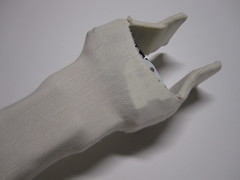
Only skin.
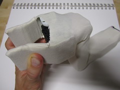
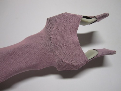
Only flesh.
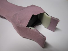
Flesh and skin can stretch all the way over hand as well.
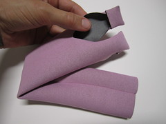
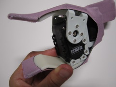
Getting dressed. Stretched skin.
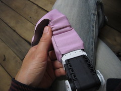
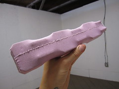
Possible ways of connecting or stretching skin/flesh across limb.
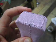
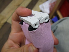
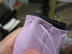
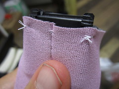
Skin grid.
Full Robot Arm Arrives (14.10.2011)
Full Robot Arm Arrives (14.10.2011)
0.5mm Neoprene (6.10.2011)
Pink! But sadly only lined on one side.
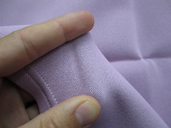
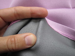
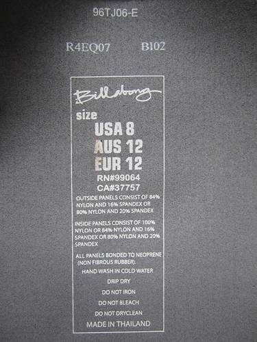
Ways of Connecting (1.10.2011)
Robot skin to arm…
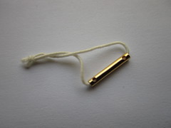
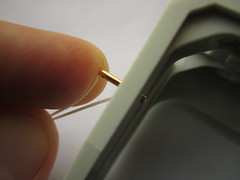
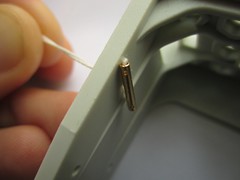
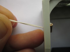
Wires to fabric…
Copper rivets >> http://www.metalclayfindings.com/product.aspx?id=321
>> http://www.mcmaster.com/#copper-rivets/=ej5xcp
Neoprene (30.9.2011)
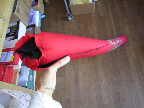
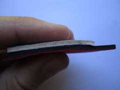
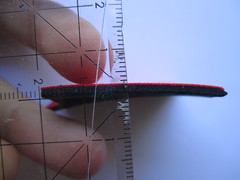
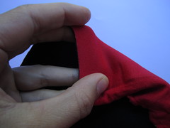
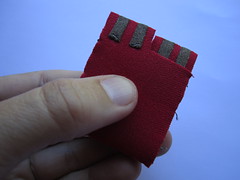
TurtleBot Arm (30.9.2011)
Link >> http://makeprojects.com/Project/Build-an-Arm-for-Your-TurtleBot/1323/1
Actual Robot Joint (23.9.2011)
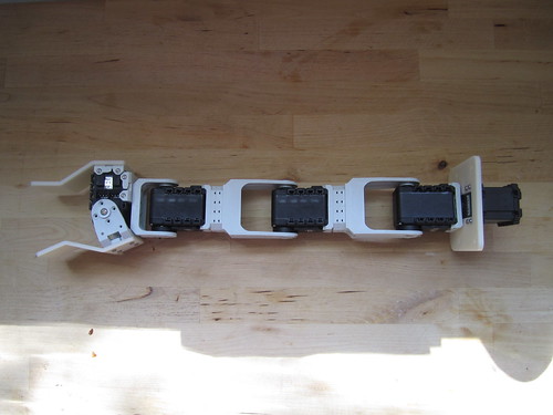
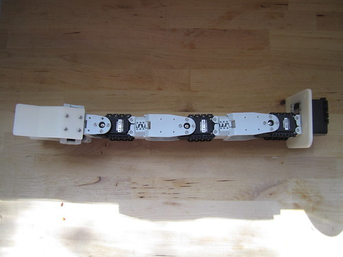
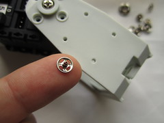
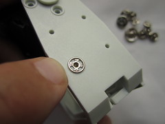
The actual robot joint/arm is much flatter than my mock-up. Somehow i had the black section rotated the other way. It is also nice to see the holes for attachment and a nice way of attaching the skin to the arm would be to use hand-sew snaps that fit the holes perfectly (unfortunately the ones in the photo are slightly too small). This way they would not inhibit the skin from being sensitive at the attachment points. If using machine snaps (these would penetrate all the way through the material) meaning that the sensitivity of the skin in that area would be compromised.
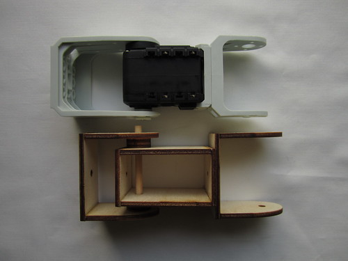
Another issue i see is that because the arm has hollows and cavities the skin will not always have something hard on both sides when it is being pressured. To some degree this could be evened out by knowing how the arm is bend, where these cavities are and compensating for the lack of pressure in code (adjusting the pressure range/sensitivity knowing that there is no bone on the other side to counter pressure). A more physical solution to this would be to really think about having a flesh layer between the arm (bones) and the sensor matrix (skin). Though for now, I think it makes sense to prototype the skin and see how well it works as is.
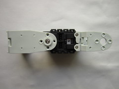
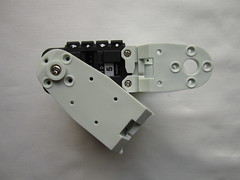
Neoprene stretched over joint. Way too bulky!
Snaps as connectors.
First fabric skin tests (19.9.2011)
I lasercut some wood parts to build a very super rough mock-up. The mock-up is nice because it gives me a much better feeling for the size, dimensions and architecture of the joint. But on the other hand it is also rather fragile and doesn’t give me a good impression of the strength and stability of the actual joint.
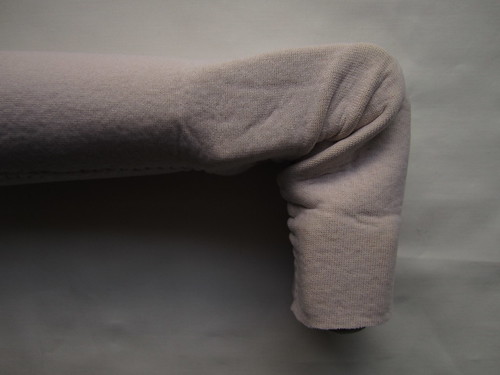
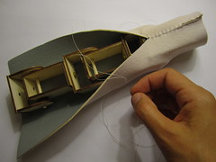
To get a feeling for how the fabric skin will move with the joint i made two fabric sleeves, one from a slightly stretchy jersey fabric and the other from 1.5 mm thick neoprene.
The jersey prototype moves quite nicely with the arm, especially when stretched at both ends, to avoid it bunching at the joint. But i am afraid of how the fabric will wear out over time. Maybe a thicker lycra fabric with good elasticity and shape retention (better word?) would be worth considering.
Arm with semi-stretchy jersey sleeve.
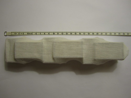
Twist and bend.
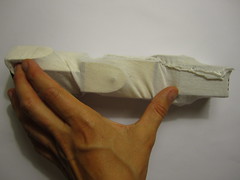
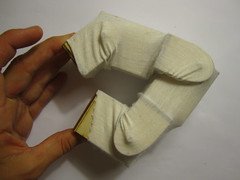
Video of jersey skin coated arm in motion
The 1.5 mm neoprene that i have at hand is too thick to deform properly with the amount of bend that these joints can handle. Although, maybe i am underestimating the strength of the joints, as my mock-up is rather flimsy.
Sewing the neoprene onto the joint.
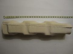
Bend
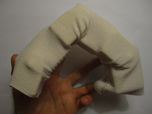
Video
One question i now have is, how much to attach the fabric to the joint and where to attach it, to what parts? This will also depend on the kind of fabric we end up using, and how much it stretches with vs. slides over the joint. Stretching it from both ends, seems like a nice way of keeping if from bunching, and in combination with fixing it at a few select points, might be a nice way to control how and how much it moves. The fabric should stretch with the joint, but not get caught on it (like it does on the inside the inner crevice of the elbow). What is missing is the flesh! A buffer that ties the skin to the bones without the skin being attached directly to the bones.
I’m excited for the 0.5 mm thick neoprene to arrive, because i wonder how stretchy and how tough it is, and maybe we should add some additional material, something with the consistency of flesh.


Wooden mock-up for testing (19.9.2011)
I didn’t want to spend too much time making a mock-up, so the following cut-file for lasercutting 1/8” plywood was done very quickly, just so that i could assemble a relatively sturdy wood mock-up for testing.
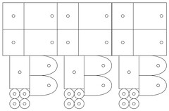
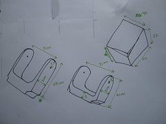
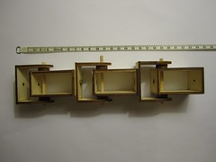
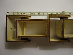
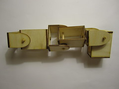
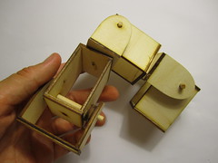
Previous cardboard prototypes proved quite ridiculous:-)
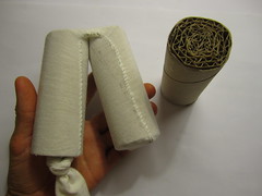
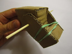
Materials and Parts (16.9.2011)
Here are some links to the materials and parts that are so far involved (or will be involved) in this project.
Sparkfun parts >> http://sprkfn.com/w25113
16 Channel through-hole multiplexer from DigiKey >> http://search.digikey.com/scripts/DkSearch/dksus.dll?Detail&name=296-3517-5-ND
Piezoresistive fabrics from Eeonyx >> http://eeonyx.com/
Conductive fabrics from LessEMF >> http://lessemf.com/fabric.html
Flexible wires from McMaster >> http://www.mcmaster.com/#flexible-wire/=e3brfw
0.5mm Thick neoprene from Foamorder >> http://www.foamorder.com/neoprene.html#colors
Servos >> http://support.robotis.com/en/product/dynamixel/ax_series/dxl_ax_actuator.htm
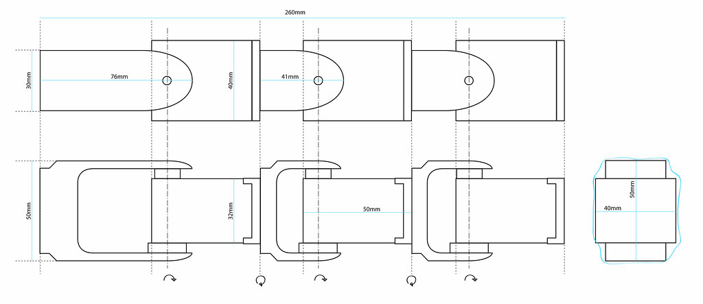
Dimensions (14.9.2011)
Larger view >> http://www.flickr.com/photos/plusea/6150889596/sizes/o/in/photostream/
Finishing the matrix code (13.9.2011)
This first example of a 8×8 matrix was mostly for the purposes of getting the code for the multiplexer setup and the visualization done. This small prototype is made using knit needle-stripe conductive fabric from plug and wear. The conductive stripes in the fabric are knit with a very thin flexible wire. Unfortunately the wire was not that great to solder to (they have a fabric breadboard fabric, that uses a copper wire and is much better for soldering to), so I skipped every other conductive knit row. The nice thing about this fabric is that it can be industrially produced and the connections to the conductive traces can be soldered. The fabric is not very stretchy, but i could imagine that it could be made more so.
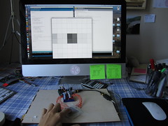

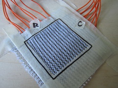
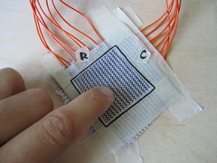
Video (now with captions!)
The next versions of this matrix will focus on stretch and getting it to work on the robot arm prototype. I think that the thin sheet of neoprene will work well, because it is stretchy but also strong enough to limit the bend of the joint, to a radius that it can manage. Although it could become a problem if it is not stretchy enough.
Another option is to use a thinner and more stretchy fabric like a stretchy nylon or jersey. The problems i see with this, is that the fabric will crunch and wear at the joint.
For fun (7.9.2011)
Some reading:
Telemetric Robot Skin – mix and mold
A Tactile Sensing Element for a Whole Body Robot Skin
A Sensitive Skin Using Wireless Tactile Sensing Elements
An Embedded Artificial Skin for Humanoid Robots – rectangular modules
Digital Tactile Sensing Elements: Communicating through Conductive Skin Layers
Row and Column Location Sensing (6.9.2011)
The following experiments show a textile row and column approach to pressure and position sensing. This approach is not dissimilar to the Unmousepad or Kevin Chiu’s multi-touch wall paper, only that it is fabric and should be able to stretch without influencing pressure and location values (too drastically).
Unmousepad and multi-touch wallpaper:


Sketch:
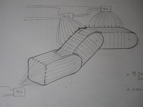
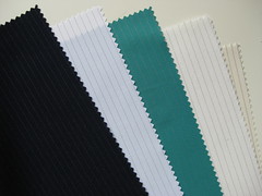
Foamorder sells 0.5mm thick neoprene with nylon fused to either side. This is much thinner than the 1.5mm thick neoprene that i’ve worked with in the past, and i think it will make a great stretchy (but not too stretchy) fabric to base this sensor on. Because it is a robust textile, i think it will also do a good job of allowing the joints to bend, but also to limit the range of their bend naturally because of the stretch limitations of the fabric. What would make this approach nicely manufacturable would be to find a ready-made stretchy fabric with conductive pin-stripes, similar to what Heathcoat and Toray produce. Only unfortunately neither of the samples i have of their fabrics are stretchy. Neoprene is a vulcanized rubber that normally comes with a jersey or nylon fabric fused to either side, and i know it is possible to have neoprene companies fuse custom fabrics to the neoprene and this might be a way of combining the benefits of the neoprene with a manufactured row/column conductor solution!
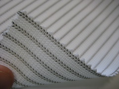
Toray and Heathcoat pin-stripe conductive fabrics:
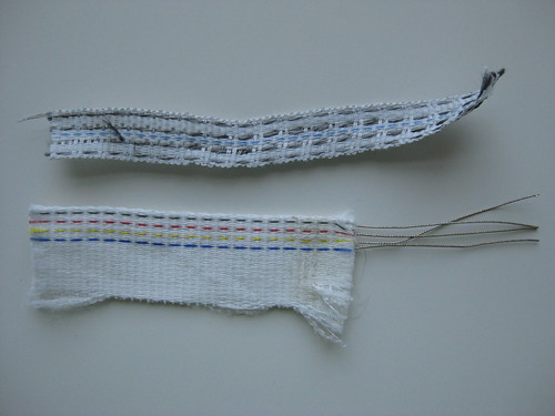
Offray produces narrow fabrics, some of which are stretchy and contain multiple conductive leads:
Thinking of ways to make attaching the individual conductive traces (rows, columns) to the multiplexers (via wire) easier than having to stitch to them each time with conductive thread…
Punch grommet/eyelet/rivets through the fabric and then solder to them >> http://www.mcmaster.com/#standard-rivets/=dy79ed
Found this great photo of fabric rivets on the web, but no idea where to get them from:
>> http://www.topfreebiz.com/product/688440/Fabric-and-Leather-with-Rivets-Eyelets-O-Ring-1.htm

Have the pin-stripe traces be made from a solderable conductive thread (thin wires), such as those from Karl Grimm >> http://www.karl-grimm.com/navi.swf
And then solder flexible wires to the solderable thread >> http://www.kobakant.at/DIY/?p=1720


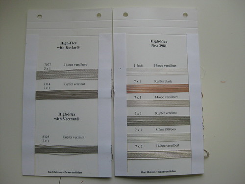
Copper plate non-solderable conductive thread or fabric traces >> http://www.kobakant.at/DIY/?p=2999


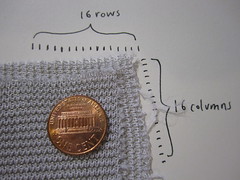
Plug and Wear actually manufactures a fabric breadbaord that is made of alternate conductive and non-conductive knit rows. The conductive rows are knit with a thin flexible wire, and they can easily be soldered to. The spacing of the conductive rows matches that of standard electronics components, which means about three conductive rows per cm. This could be a really nice option, and it can be left up to the person applying the robot skin to their particular project, how much resolution they want and thus whether they connect every conductive row (ca 2 mm resolution) or every other (ca. 5mm resolution). >> http://www.plugandwear.com/default.asp?mod=product&cat_id=89,103&product_id=80
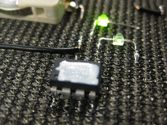

Plug and Wear also sells a flexible perfboard strip >> http://www.plugandwear.com/default.asp?mod=product&cat_id=95,101&product_id=116

I like the idea that you could purchase a tube, cut it to your desired length, solder/rivet/connect to as many rows and columns as you want resolution and connect these to multiplexer modules that carry all the data to a central point. The only thing i don’t like is that you have all these wires sticking out. I see that the robot arm already has some wires running alongside it, so maybe this is not the end of the world. But i also see each wire as a potential problem. With e-textiles in particular, every hard/soft connection presents an opportunity for error. Maybe a third layer of skin could work as a bus line, carrying all the circumference columns along the arm and back to one area. Maybe there would also be a way of embedding the multiplexer right into the fabric, so that each 8×8 matrix section would only need 7 connections (power, ground, COM and A, B, C, D). Though 7 is still a lot for an 8×8 grid, if you might end up having 6 of them to cover your whole arm.
Because of the many contacts that accumulate (one for each row and column), a module approach starts to make sense, where each module (a section of skin) has 16 rows and 16 columns that connect via 16-channel multiplexers to a single microcontroller. To avoid the need for external pullup resistors (one for each multiplexer, which is not that many, but still), i’m looking to find a piezoresistive fabric that will work well in the range of the internal pull-up resistors, which are 10-20K Ohm.
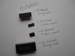
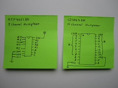
Multiplexers:
The 16 channel multiplexer requires 7 connections to read 16 channels (rows and/or columns of data), these are power, ground, COM and A, B, C, D control pins.
The 8 channel multiplexer requires 6 connections to read 8 channels, these are power, ground, COM and A, B, C control pins.
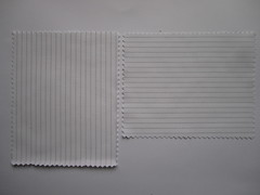
Toray woven fabric (not solderable)

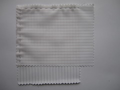
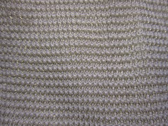
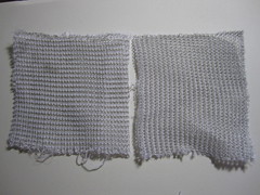
Plug and Wear knit fabric (solderable!)
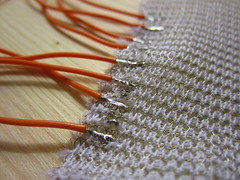
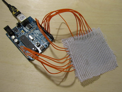
Resistive Location Sensing (6.9.2011)
The following experiments show the use of a simultaneously resistive and piezoresistive material (an Eeonyx Eeontex coated fabric) used to detect location of contact by measuring resistance between contact point and each of the fabric square’s four corners. I think the results look very promising, most of the inaccuracy is simply due to my poor math and programming skills. To further improve accuracy it should also be possible to use the pressure information to cancel out unwanted pressure related variations from the resistive location data. Overall i believe this solution could be much improved with some more work on the end of analyzing and mapping the sensor data. On the other hand, with this approach it would not be impossible to to gather data from multiple discrete points of contact at the same time (multi-touch). So even though this approach would immensely reduce the number of contacts needed for resolution, multi-touch seems like one of the best arguments in favor of the row/column location sensing approach – which i will try next.
First test
Based on the Knit Touchpad and an experiment using a circular piece of Velostat.
Using Eeontex RP-3-125-2B piezo/resistive fabric, which was one of the least sensitive to stretch sensing (number #8 on the stretch chart). Not being sensitive to stretch, makes it good for distance/location sensing.
Knit Touchpad and Velostat circle:
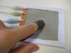
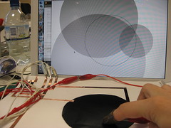
First test using Eeontex:
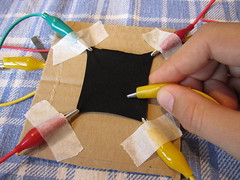
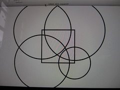
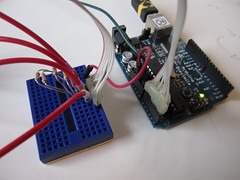
Setup using an Arduino Diecimila and external 780Ohm pullup resistors:
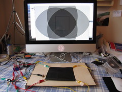
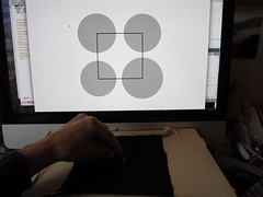
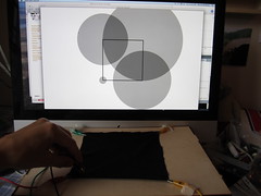
The following video shows a visualization of the resistance values measured from all four corners used to draw circles, their radius is the unfiltered sensor input, scaled to fit the square dimensions.
Linearizing sensor data
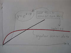
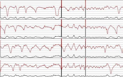
The change in resistance of the Eeontex is close to a logarithmic function, the less distance between measuring points, the more range, the further away the measuring points are the range (change in resistance) becomes less.
mappedValues[i] = map(transferValues[i], 0,1023, 0,7); // map the incoming values (0 to 1023) to a graphing range for the following calculation
linearValues[i] = exp(mappedValues[i]-4); //change from log to linear
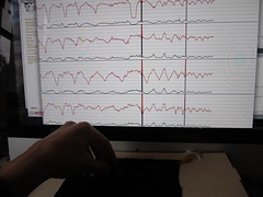

Some stills of the visualization
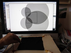
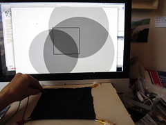
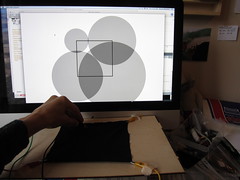
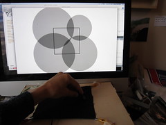
In the following video the red graph lines are the incoming sensor data and the black lines are their linearized version.
The following videos shows the same mapping as previously but this time with the linearized sensor data described above.
Eeontex fabric:
Velostat:
Layering and spacing
Looking for materials to build the sensor from. Soft, light and stretchy conductive fabrics from LessEMF include: silverized lycra, silverell, see-through conductive fabric, silver mesh fabric, veilshield.
Although the best spacer material to use will best be determined by the final design of the fabric skin and how it attaches to the robot arm. How much pressure is involved in the initial fastening and what level of initial sensitivity is desired. The thicker and firmer the spacer material, the more initial pressure is needed to trigger the sensor. Spacer materials tested so far include perforated foams with different thicknesses and consistencies, loosely woven fabrics and webbing.
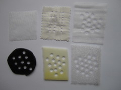
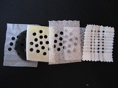
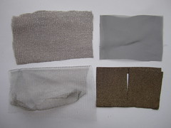
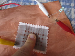
Bottom and top spacing layers in test setup
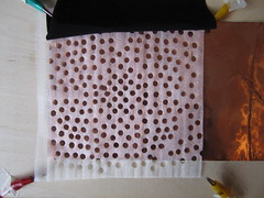
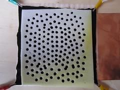
Bottom conductive layer is a sheet of copper tape, testing different conductive fabrics on top.
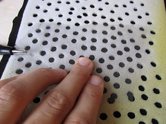
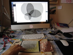
Adding pressure information
The red bar to the left of the touchpad square represents the amount of pressure applied (no matter what location). While the location sensor data has been linearized, the pressure data is not (yet).
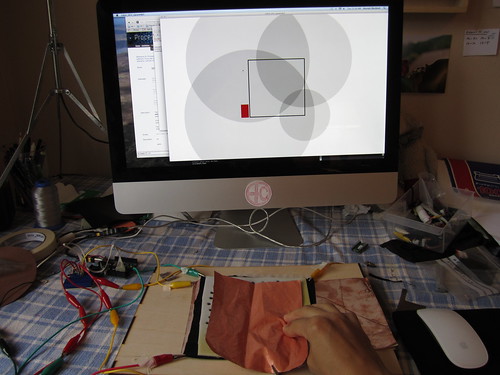
The following video shows both location and pressure information:
Here is the schematic i used:
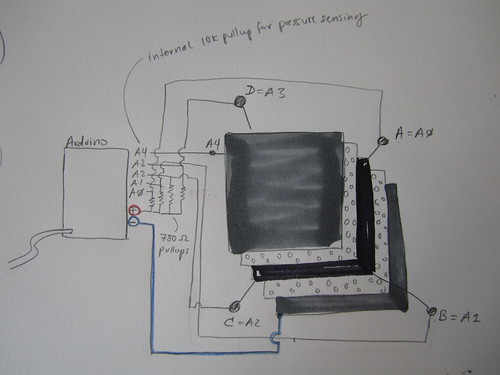
First mock-up of robot arm (3.9.2011)
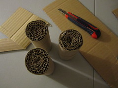
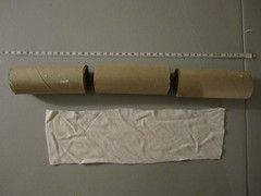
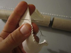
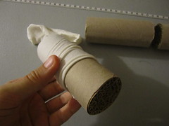
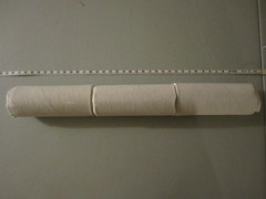
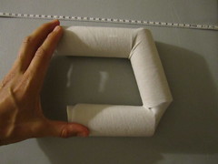
Sketches (3.9.2011)
Materials
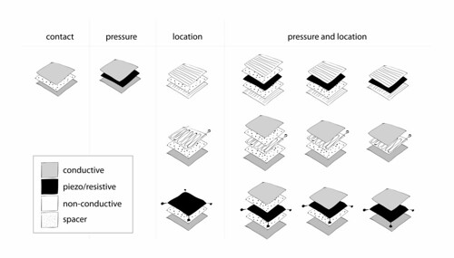
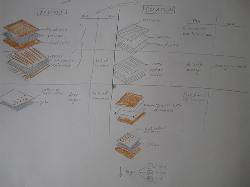
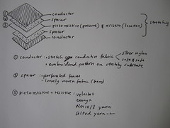
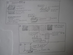
This sketch shows some of the variations of pressure and location sensors made by layering conductive and piezo/resistive materials. Piezoresistive materials change electrical resistance under mechanical stress (pressure, bend, stretch…). When i refer to resistive materials, i normally mean materials that have increasing resistance over distance. While resistive materials don’t necessarily have piezoresistive properties, piezoresistive materials are normally also resistive. Most of the piezoresistive materials i’ve worked with are piezoresistive only in their z-axis (through the material) and not in their x/y-axis (across their surface). So i am hoping that it will be possible to use such a piezo/resistive material, to measure both change in pressure as well as location.
Conductive material: stretch conductive fabrics (silverized nylon, soft and safe…), conductive threads
Resistive materials: resistive thread from LessEMF, resistive yarn from Plug and Wear
Piezo/resistive materials: Velostat, Eeonyx fabrics
Spacer materials: perforated foam, loose woven fabrics, silicon dots…
Non-conductive/isolating materials: jersey fabric….
Resolution
While using a row and column grid/matrix structure within the layering to determine position can be very accurate, one accumulates a lot of contacts and resolution is limited by the number of contacts one is willing or able to include. Having a continuous, resistive surface or space-filling curve reduces the number of contacts to three or less. Because it is not made up of discrete points, resolution depends on reliably one can detect differences in distance.
Non-linearity
Most piezo/resistive materials are not linear in their resistive changes (distance/stress). Mapping the resistance values from the sensor skin to a model will definably also play a roll in how well the data appears.
Setup
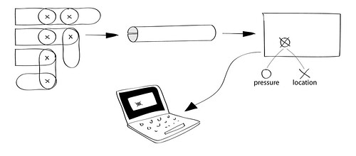
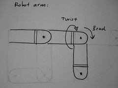
Here is a sketch of the very basic setup and idea. The robotic arm (with two joints) which can bend and twist should be covered in a textile skin. The skin will most likely be a stretchy fabric tube that fits snugly over the robot arm. For simplicity of construction, the tube is folded rectangle, consisting of various layers of conductive, resistive, piezoresistive and isolating materials.
Data from the robot skin is sent to a computer application that visualizes sensor data.
Brainstorming
Project Summary
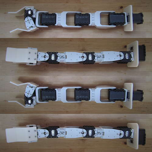
The aim is to prototype a textile skin that can stretch over or otherwise be attached to robotic arm, like the one pictured bellow. The skin should be able to stretch and twist as the joints of the arm move while simultaneously being able to detect contact with other objects. Gathering both location and pressure intensity data. While bending, stretching and twisting of the skin itself will influence the readings, it should not render them useless. This robot skin aims to imitate human skin both in functionality as well as look and feel.
Summary of criteria and goals for the robot skin:
– reliably detect both location and impact/pressure of objects touching the robot skin
– detect location on the skin at the highest resolution possible (5mm sq or less would be great)
– detect pressure intensity within the range of objects the robot might interact with (keys and chairs, not elephants and feathers)
– be cheap to manufacture (low material and production costs)
– attach to the robotic arm featured in the picture bellow, but also be customizable for people’s unique designs
– ideally the skin will be stretchy, and stretching of the skin does not influence the location and pressure readings
Example of robotic arm

