Penguin Progress Blog
<< Project Page
>> Flickr Photo Set
>> YouTube Video Playlist
>> Instructable
>> GitHub Code and File Repository
Next Steps…
– Electronics as insert
– Outer penguin washable
– Optimize stroke sensor
Yingdan Huang’s PlushBot >> http://www.plushbot.com/
PlushBot tutorial >> www.plushbot.com/PlushbotTutorial.pdf
Plushbot – Cute kitty from Yingdan Huang on Vimeo.
HLT Interactive Robots workshop >> http://hlt.media.mit.edu/?p=1886
Penguin discovers electronic music
By Harlan Iverson
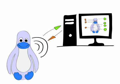
Penguin as HID Bluetooth Keyboard
Using Sparkfun’s Bluetooth Modem – BlueSMiRF HID to interface between an Arduino Pro Mini and a desktop Computer. Also see: Arduino as Bluetooth Keyboard post >> http://www.kobakant.at/DIY/?p=3310
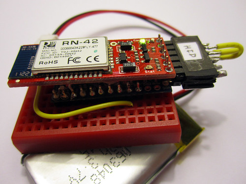
Setup Instructions
Program Arduino
Upload the following code to the Penguin Arduino. The code has been simplified for demo purposes.
Arduino HID Penguin Code >> https://github.com/plusea/Penguin-Interface/blob/master/code/a_penguin_HID/a_penguin_HID.pde
Key commands:
Squeeze or hug penguin body –> “Enter Key” – each squeeze is one key press – set sensor thresholds in code
Tilt upright –> Neutral position
Tilt back –> “Down Arrow” – repeats key press every X seconds, default to 0.5 sec – set timing in code
Tilt right –> “Right Arrow” – repeats key press every X seconds, default to 0.5 sec – set timing in code
Tilt left –> “Left Arrow” – repeats key press every X seconds, default to 0.5 sec – set timing in code
Squeeze or bend both wings –> “Up Arrow” – repeats key press every X seconds, default to 0.5 sec – set sensor thresholds and timing in code
Simulated output:
Squeeze or hug penguin body –> vibrate motor – set sensor thresholds in code
Squeeze or bend right wing only –> when pressured toggle between red, green, blue and white LED light, when released turn light off – set sensor thresholds in code
Squeeze or bend left wing only –> play melody – set sensor thresholds in code

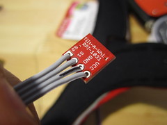
Connect HID Bluetooth Modem to Arduino with Adaptor
BlueSMiRF HID >> Arduino Mini:
RTS >> GRN = CTS
RX >> TX
TX >> RX
VCC >> VCC
CTS >> GND
GND >> BLK = GND
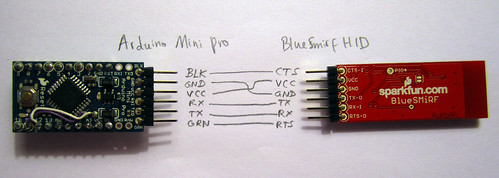
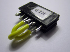
Make a simple adapter:


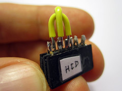
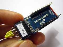

Pair with Bluetooth Device
Pairing Bluetooth device on Mac >> http://www.rioleo.org/setting-up-the-arduino-pro-mini-and-bluetooth-mate-on-mac.php
Pairing Bluetooth device on Windows >> http://jondontdoit.blogspot.com/2011/11/bluetooth-mate-tutorial.html
Steps:
– power your circuit and the light on your Bluetooth modem should blink red
– open the Bluetooth preferences of your computer and opt to pair with a new Bluetooth device by pressing the “+” at the bottom of the Bluetooth device list

– the circuit should show up as a FireFly Bluetooth device with an address similar to this: FireFly-A229
– press continue to begin pairing process

– when the attempt to pair with the device fails, opt to connect with pass code by pressing the Passcode Options button at the bottom left of the window

– type “1234”, which is the generic pass code

– once successfully paired the light on your BlueSmirf Modem should turn a steady green

– the first time i paired the FireFly modem with my computer it tried to identify it as a keyboard and was asking me to press the button next to the shift key. since this was not possible to do on the modem, i instead pressed a random button on my real (other) keyboard, which it didn’t recognize and then let me skip the step and manually input the type of keyboard i wanted the module to be recognized as
– the Bluetooth module should now show up as follows in your Bluetooth device list:

Re-Connecting
When i disconnect the Bluetooth modem from the power, my computer does not automatically re-connect to it when i re-power it.

I have to go back into the Bluetooth preferences and opt to add a new device, then select “Okay” when asked “Your computer is already paired with that device. Do you wish to remove the pairing and setup the device again?”

Next Steps…
How does the computer SEND commands TO the Penguin?
The Bluetooth modem needs to switch back and forth between an HID device and a device with a serial port connection (SPP mode). For this to happen the Arduino needs to put the Bluetooth modem into command mode ($$$) and send the following commands:
$$$ = command mode
S~,0 = enables SPP protocol
R,1 = reboot using SPP
$$$ S~,0 R,1
$$$ = command mode
S~,6 = enables HID protocol
R,1 = reboot using HID
$$$ S~,6 R,1
Penguin as Bluetooth Device (non HID!)
Arduino code running on the Arduino board >> https://github.com/plusea/Penguin-Interface/tree/master/code/a_penguin_send2
Basic setup:
– unzip the back of the penguin
– connect the Bluetooth module to the Arduino so that it looks like this:
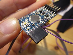

– connect the battery to the battery board:
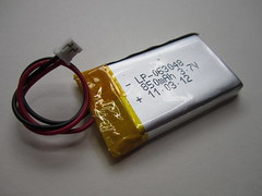

– power the penguin circuit, by turning the switch on the battery board “on” (the Bluetooth module should light up and blink red)
– open the Bluetooth preferences of your computer and opt to pair with a new Bluetooth device
– the Penguin should show up as a Bluetooth device with the following address: “/dev/tty.RN42-E59C-SPP”
– opt to connect with passcode and type “1234”, which is the generic passcode
– once paired successfully you can now interface with the penguin either via the Arduino serial monitor or via the processing application.
– once the Penguin has paired successfully with your computer you can zip it back up at anytime, but before doing so you might want to re-arrange some of the sensors and actuators
– the sensors and actuators are intentionally mounted on long wires so that we can test different placements to determine best placement, here are some suggestions for best placement:
* the LED light should go where the heart is
* the tilt sensor can go anywhere but should be oriented so that tilting the penguin triggers the right directions
* the vibration motor should go close to the belly of the penguin so that it can be felt when holding the penguin close
* the squeeze sensor should go right in the middle of the stomach, or wherever the most squeeze is happening
* the bend sensors should go in the wings
* the speaker can go anywhere
Talking to Penguin via Serial Monitor
– Download and install arduino
– Run the Arduino software and open the serial monitor
– in the lower right hand corner set the baud rate to “115200”
– the Serial Monitor should start printing lines of numbers, which mean the following:
rightBendAmount [0,1,2,3], leftBendAmount [0,1,2,3], squeezeAmount [0,1,2,3], tiltDirection [1,2,3,4], accelerometer X [0-1023], accelerometer Y [0-1023], accelerometer Z [0-1023]
– at the top of the serial monitor you can type and send characters
– the following characters should trigger the following Penguin events:
r = red light
g = green light
b = blue light
w = white light
z = light off
q = quiet melody
m = moderate melody
l = loud melody
n = melody off
t = timid vibration
v = medium vibration
h = hard vibration
s = no vibration
Talking to Penguin via Processing Application
The processing application is basically the GUI interface for the above scenario using the serial monitor.
– download and install the processing software, open the following sketch:
processing code for application >> https://github.com/plusea/Penguin-Interface/tree/master/code/p_penguin_vis
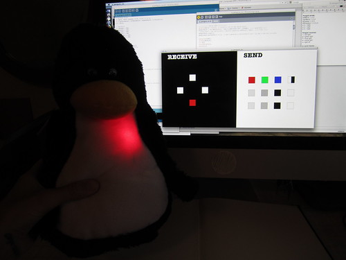
– run the sketch and a new window should open and look like this:
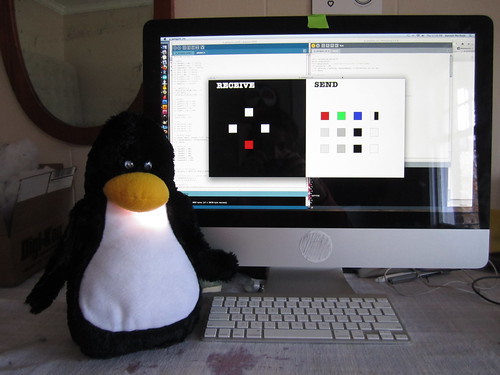
– the left side of the window with the black background visualizes the sensor data from the penguin
– the right side of the window with the white background allows you to send data to the penguin by clicking on the various boxes:
first row) LED: red, green, blue, white and off
second row) SPEAKER: low, medium, high, off
third row) VIBRATION MOTOR: low, medium, high, off
Photos and Video

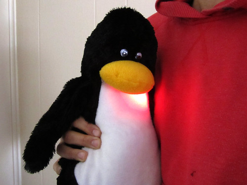
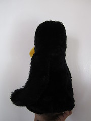
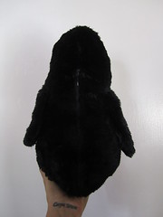
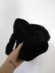
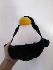
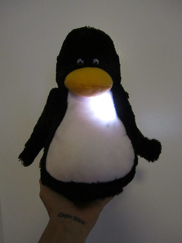
From all sides
Send and Receive

Video
Penguin Talking
Video: Testing Innards
Video: First Words
In the “send” part of the application window, clicking on…
…the first four boxes trigger different colors of the LED light (red, green, blue, white and off)
…the second row of boxes trigger the melody to play in three different pitches, as i currently can’t control volume
…the third row of boxes trigger the vibration motor at three different intensities
Talking with computer…
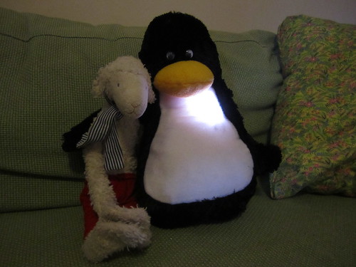
Talking with Sheep…
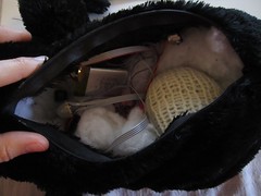
Insides
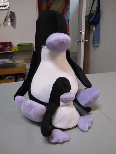
Bigger Penguin
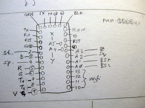
Connections:
INPUTS
Bend Sensor Left (BSL) – A0
Bend Sensor Right (BSR) – A1
Squeeze Sensor (squeeze) – A2
4-way tilt (T1, T2) – 7, 8
Stroke sensor (stroke) – 2
Beak pushbutton (beak) – ?
3-axis accelerometer (x,y,z) – A3, A4, A5
OUTPUTS
RGB LED (R, G, B) – 5, 6, 3 (pwm)
Speaker (speaker) – 4
Vibration motor (vibe) – 9 (pwm)
COMMUNICATION
WiFly Shield – 10, 11, 12, 13
BlueSmirf HD – RX, TX
Manually adding wings
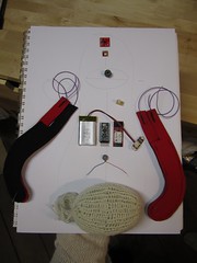
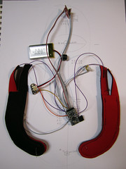
Before and after soldering.
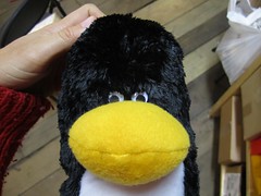
Positioning eyes.

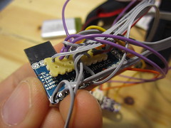
Arduino with all connections wired. 4-pin female header for Wifly shield connection.

4-axis gryo and speaker
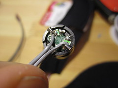
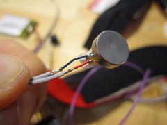
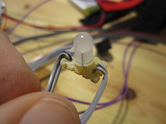
Vibration motor and LED in hot glue

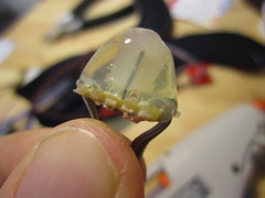
Squeeze sensor.
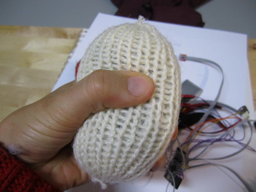
Bend sensors.
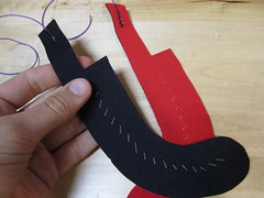
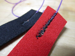
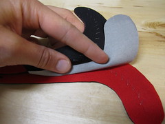
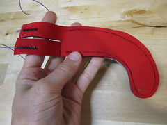
Adding the zipper.
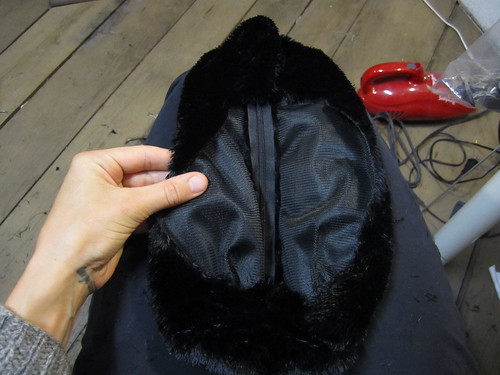
The long black fur is a real pain to work with, it get everywhere and is shiny black and hard to see the edges of the fabric when you are sewing. But it looks and feels great.
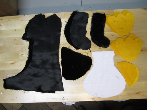
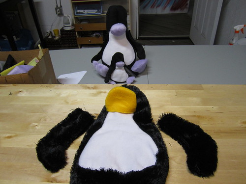
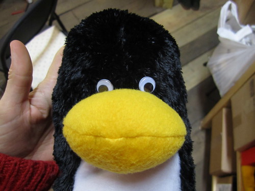
Longer fur and fleece beak, looks much better. I am thinking of leaving the feet, as they are not a functional part of the interface and look somewhat clumsy.
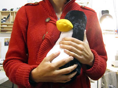
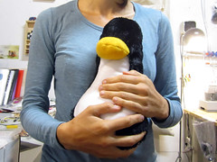
Bigger penguin with short fur does not look so good.
Updates
Penguing = HID Bluetooth Keyboard
Bluetooth Modem – BlueSMiRF HID >> http://www.sparkfun.com/products/10938
Bluetooth (and Wifi) Communication Protocols between Penguin and Computer Application
Penguin to computer:
tilt back –> up cursor
right –> right cursor
tilt left –> left cursor
tilt upright –> down cursor
accelerometer shake –> sh#### (or 4,5,6) shake intensity
squeeze –> enter key + sq#### (or 1,2,3) intensity of squeeze
stroke –> space bar
beak button –> “B”
Computer to penguin:
vibe(intensity, duration)
melody(melody#, volume, duration/repeat)
ledRGB(red[0-255], green[0-255], blue[0-255])
ledMode(0=off,1=on,2=blink,3=fade)
ledBlink(duration on, duration off)
ledFade(duration on, duration off)
Sensors (inputs)
Arduino pro mini: 16 (or 20) digital i/o, 6 analog in
– 4-way tilt sensor in head or body (digital, 4)
– 3-axis accelerometer in head or body (analog, 3)
– knit squeeze sensor in tummy (analog, 1)
– fabric pushbutton in beak (digital, 1)
– neoprene bend sensors in wings (analog, 2)
– stitched stroke sensor on head (digital, 1)
total inputs: 12
Actuators (outputs)
Arduino pro mini: 16 (or 20) digital i/o, 6 PWM outputs (pins=3,5,6,9,10,11)
– RGB led as heart in chest (PWM, 3)
– vibration motor in body (PWM, 1)
– speaker in head (digital, 1)
total outputs: 5
Updated schematic (incorporating all of the above):
Debouncing code for tilt sensors >> http://arduino.cc/en/Tutorial/Debounce
Penguin Schematic
I’m thinking of re-designing the circuit to use the Arduino Mini Pro instead of the LilyPad.
Not all of the following parts need to be purchased, some of them are in there for comparison:
Updated parts list >> http://www.sparkfun.com/wish_lists/28553
LED wiring >> http://wiring.org.co/learning/basics/rgbled.html
Textile sensors:
Squeeze sensor (resistive sensor with range from 10K – 100 ohm) >> http://www.kobakant.at/DIY/?p=3175
Neoprene bend sensors (resistive sensors with range from 20K – 200 ohm) >> http://www.kobakant.at/DIY/?p=20

Penguin Dance
Talking to Penguin via Bluetooth
Penguin talking… coming soon…
Talking to penguin:
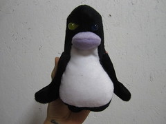
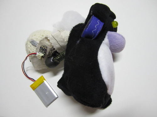
Inserting the guts into the penguin:
First test of circuit
Some updates to circuitry
Replaing neoprene pressure sensor with squeeze sensor and beaded tilt sensor with commercial one:
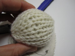

Isolating squeeze sensor inside an extra ball:
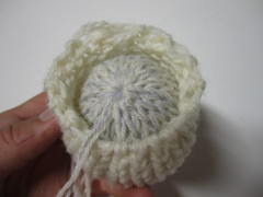
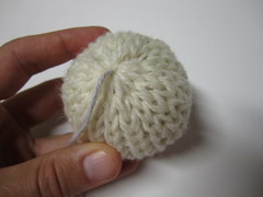
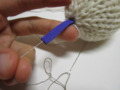
Stitching through neoprene as an isolator for conductive thread:

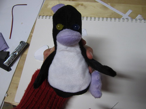
Sewing feet is not so easy

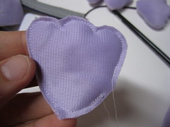
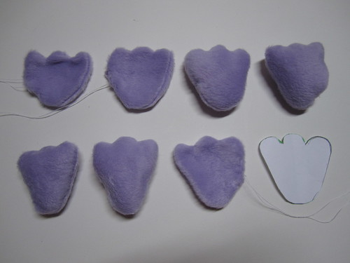
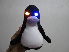
Looks a bit evil. Will need to fix that.
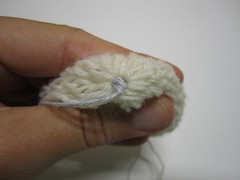
Squeeze Sensor
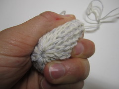
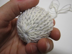
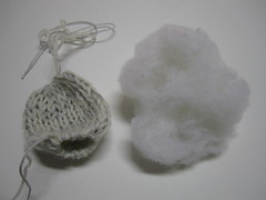
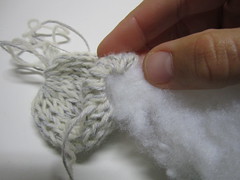
The neoprene pressure sensor was not sensitive enough to squeezing the penguin body so i tried some different variations of the knit Nm10/3 resistive yarn to make a squeeze sensor.
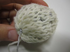
In this version of the above, the non-conductive ball is knit on a circular knitting machine, rather than crochet.
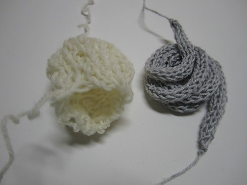
In this version a non conductive circular knit tube is stuffed with a spool-knit tube of Nm10/3 conductive and regular non-conductive yarn.

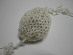

In this version the Nm10/3 conductive yarn is knit on a circular knitting machine alongside a regular white yarn. the tube is then stuffed with non-conductive stuffing and pulled tight at either end.
Smaller Penguin


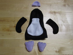

Electronic Guts
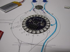
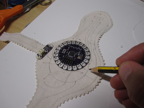
My plan for integrating the electronics inside the penguin is to have a base substrate that fits inside the penguin and carries all the electronics.
Circuitry Working
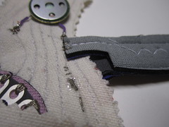
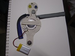
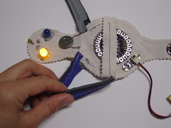
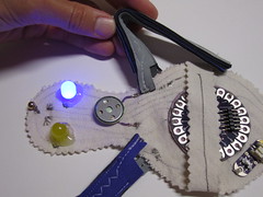
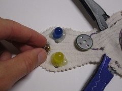
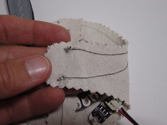
Video
Sketching layout of electronic guts:
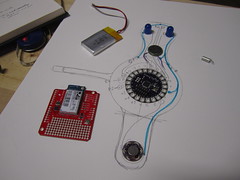
Transferring sketch to fabric:
Front and back:
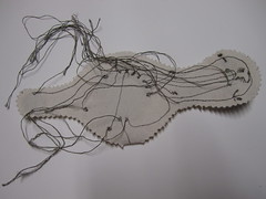
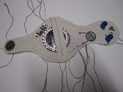
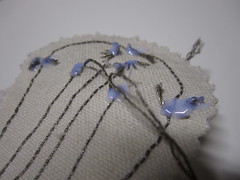
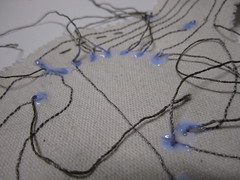
Close-ups of sewn connections:
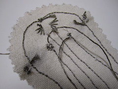
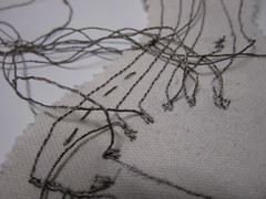
Glue on knots to make sure the thread does not fray or come undone:
INPUTS: Machine sewn bend and squeeze sensors, stitched shake sensor:
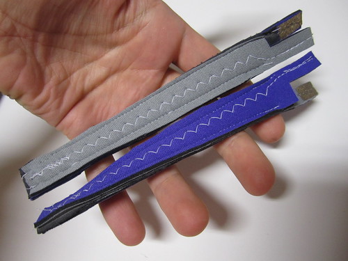
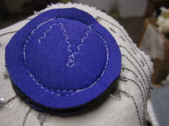
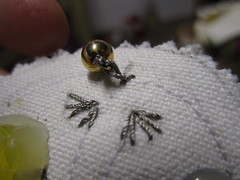
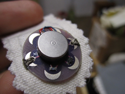
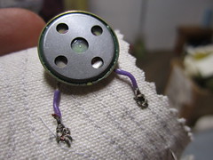
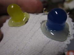
OUTPUTS: Vibration motor, speaker and LED lights:
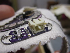
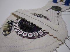
Power supply board and LilyPad Arduino:
The Pattern
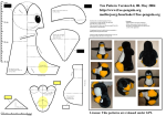
The pattern in original size is too big for my liking, the penguin comes out at about 35 cm height. I will try scaling it down to half the size.



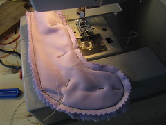
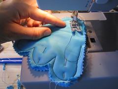
Tracing the Pattern
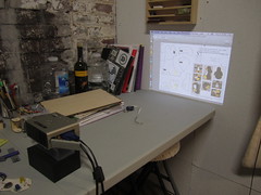
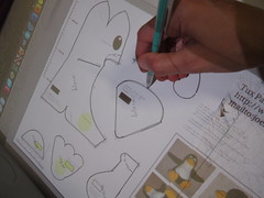
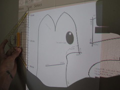
Projecting the penguin sewing pattern in order to trace it onto paper.
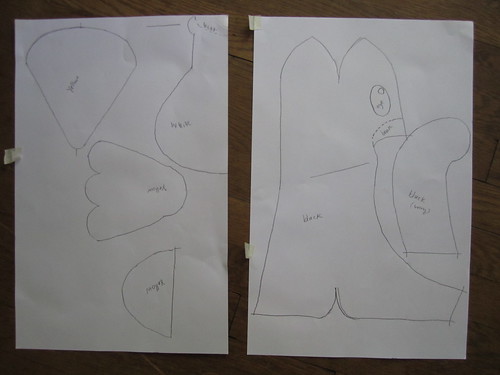
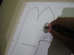
Open Source Soft Toy Penguin
Free Linux Penguin >> http://www.free-penguin.org/
Download pattern >> http://www.free-penguin.org/downloads/TUX_pattern_0.6_a1.pdf

Sourcing Materials
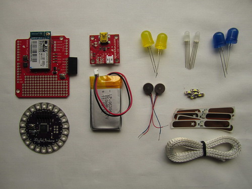
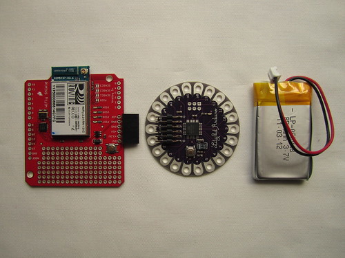
Electronics
Electronics from Sparkfun >> http://www.sparkfun.com/wish_lists/25111
Fabric and Stuffing
Stuffing from Amazon >> http://www.amazon.com/Morning-Glory-5-Pound-Premium-Fiberfill
Finding fabric is not so easy, the following fur is from fabric.com
>> http://www.fabric.com/apparel-fashion-fabric-faux-fur-fabric-soft-fur-fabric.aspx


First Sketches
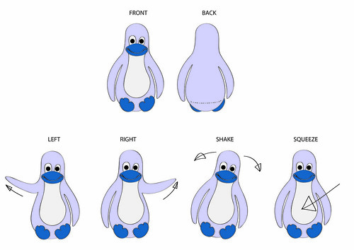
Actions
Electronics: hardware, sensors and actuators

Setup, wireless communication
