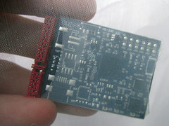
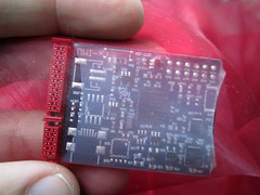
Suit Version 2 (2012)
Rachel’s sketches


Images of Rachel Freire’s work
Taken from >> http://rachelfreire.com/


New materials for glove
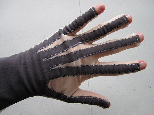
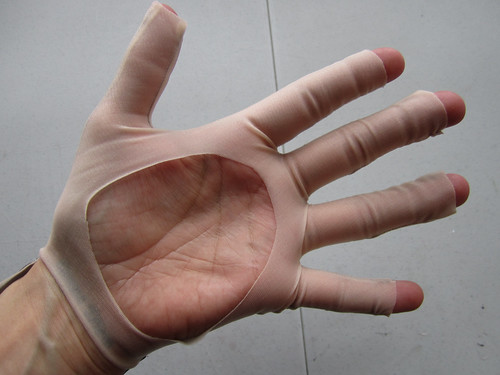
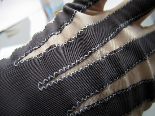
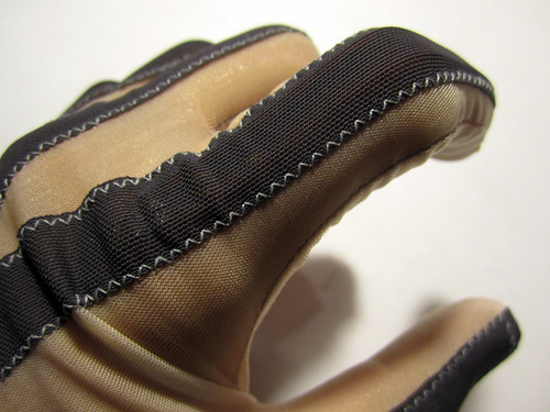
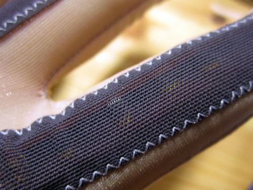
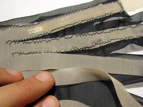
The netted fabrics are slightly stiffer than the lycra used in previous glove, so that the glove bunches and wrinkles in not so nice looking ways. Also, my sewing machine is skipping stitches on it, so that the seams look terrible. Have tried all the different kinds of needs that i had at hand, but not much difference.
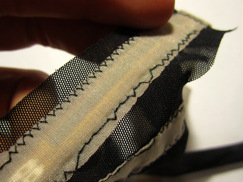
Inserting the sensors behind the netting, they aren’t all that visible. Maybe we can find a looser, more transparent netting for the fabric used to cover the sensors. Or maybe we can coat the netting in a silicone that makes it more transparent?
* Vibration motor for tactile feedback
– any ideas on where it would be good to place this?
From Tom:
“I had a thought about the tactile feedback for Imogen. Kelly is designing new control modes where Imogen’s hands pass through lots of different regions but there’s currently no feedback. So we were thinking about a tactile feedback device along the lines of the one that you included in the original designs – image attached – it would be useful to pulse the motor when a boundary is crossed. These could be driven by the remaining PWM channel…
It would be great to have independent LED and motor control for each glove – but I realise this is quite unlikely for the this phase but I thought I’d throw it out there just in case anyone has a brainwave… Maybe we can use only two channels for the LED colours and use flashing to indicate the mode…”
NOTES
Shared spreadsheet >> https://docs.google.com/spreadsheet/ccc?key=0AtJnxpXitWKSdDZURVBhNGtqNDY5eFAzRkNnVi1zV2c&pli=1#gid=0
New GLoves
– re-wire sensors with more flexible red/black wires
– remove old in-line circuit board and solder sensor wires directly to 14-way cable (adhering to Tom’s layout!)
– solve strain relief issue for above connection
– check resistance values of all sensors when glove is worn and determine final pull-up resistor values (with Seb)
– trim and finish ends of glove fingers (with Rachel)
– check how RGB LED is holding up
– check how vibration motor is holding up, and sew second pouch
– beautify Shapelock mic-holder
– finalize wiring of the 3 Arduinos that control the decorative lights to the x-IMU and seperate power supply (with Rachel)
– program Arduinos to communicate with x-IMU over 4-bit protocol (with Tom)
Old Gloves
– remove old in-line circuit board and solder sensor wires directly to 14-way cable (adhering to Tom’s layout!)
– solve strain relief issue for above connection
– check resistance values of all sensors when glove is worn and determine final pull-up resistor values
* Sensors should connect to identical aux-ports on both left and right gloves and not be mirrored (industry standard?)
AX0 Thumb
AX1 Lower Index
AX2 Upper Index
AX3 Lower Middle
AX4 Upper Middle
AX5 Lower Ring
AX6 Upper Ring
AX7 Little
(Upper indicates the joint closest to ends of the fingers)
* X-imu connects to the sensors via cables instead of snaps
* X-imu mounted on the wrist in a hard tray with transparent cover, instead of fabric pouch
* LEDs to be mounted further back on hand so as not to interfere with drumsticks
* Sensors should be adjusted to better align with knuckles
* Palm cut-out should be smaller and have sealed edge, as should ends of fingers
ARMS
* LEDs connect to the back x-imu and two driver boards on the backpack via cables instead of thread
* Cables wrap around the arms anti-clockwise instead of clockwise
– depends on overall new design based on rachel’s work
* Cables should go from underneath clothing to outside and connect to backhub from sides
– possibly no longer relevant
* Ends of arm-band cables should be less flappy
– possibly no longer relevant
BACKPACK
* Backpack should be shorter and radios mounted two on either side with access to volume knobs. no waist strap. no velcro
– rachel’s design!
* Incorporate additional lighting and visual effects into fabric that correspond with touching or movement
– this will probably require a separate circuit to the x-imu
* Possibly also use x-imu tray design for back-hub elements (motherboard, battery, wireless module)
Glove to x-IMU connections:
AX0 Thumb
AX1 Lower Index
AX2 Upper Index
AX3 Lower Middle
AX4 Upper Middle
AX5 Lower Ring
AX6 Upper Ring
AX7 Little
where Upper indicates the joint closest to ends of the fingers.
Radios, dimensions
The dimensions of the radios are (W x H x D):
In-Ears (upper left shoulder so she can reach volume knob): 6.25cm x 8.2cm x 2.5 cm
Vox mic (upper right shoulder): 6.25cm x 8.2 cm x 2.5 cm same form factor
Wrist packs (don’t need to be reached): 6cm x 9.25cm x 1.75cm
All packs have metal clips on the back that protrude an extra 2cms beyond the thickness indicated.
Updated backpack plans
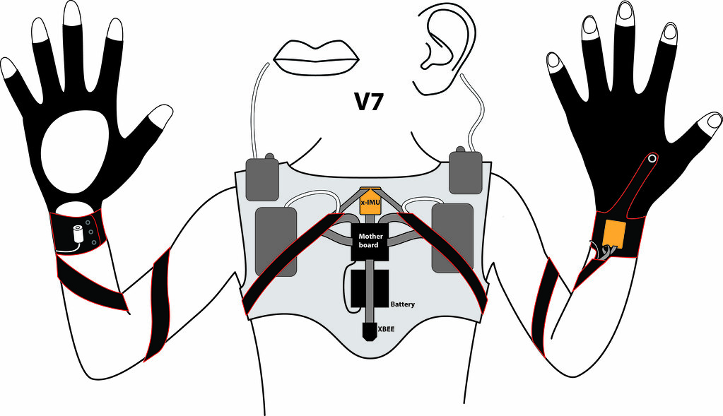
x-IMU behind translucent fabrics
