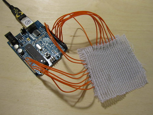
Row and Column Location Sensing (6.9.2011) (2012)
The following experiments show a textile row and column approach to pressure and position sensing. This approach is not dissimilar to the Unmousepad or Kevin Chiu’s multi-touch wall paper, only that it is fabric and should be able to stretch without influencing pressure and location values (too drastically).
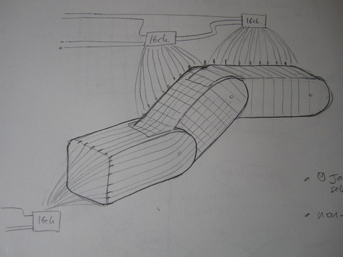
Sketch:
Unmousepad and multi-touch wallpaper:


Foamorder sells 0.5mm thick neoprene with nylon fused to either side. This is much thinner than the 1.5mm thick neoprene that i’ve worked with in the past, and i think it will make a great stretchy (but not too stretchy) fabric to base this sensor on. Because it is a robust textile, i think it will also do a good job of allowing the joints to bend, but also to limit the range of their bend naturally because of the stretch limitations of the fabric. What would make this approach nicely manufacturable would be to find a ready-made stretchy fabric with conductive pin-stripes, similar to what Heathcoat and Toray produce. Only unfortunately neither of the samples i have of their fabrics are stretchy. Neoprene is a vulcanized rubber that normally comes with a jersey or nylon fabric fused to either side, and i know it is possible to have neoprene companies fuse custom fabrics to the neoprene and this might be a way of combining the benefits of the neoprene with a manufactured row/column conductor solution!
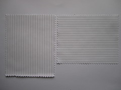
Toray and Heathcoat pin-stripe conductive fabrics:
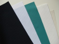
Offray produces narrow fabrics, some of which are stretchy and contain multiple conductive leads:
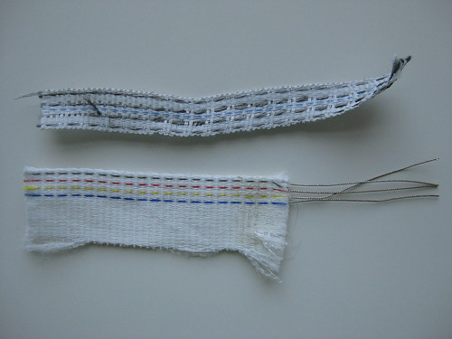
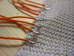
Thinking of ways to make attaching the individual conductive traces (rows, columns) to the multiplexers (via wire) easier than having to stitch to them each time with conductive thread…
Punch grommet/eyelet/rivets through the fabric and then solder to them >> http://www.mcmaster.com/#standard-rivets/=dy79ed
Found this great photo of fabric rivets on the web, but no idea where to get them from:
>> http://www.topfreebiz.com/product/688440/Fabric-and-Leather-with-Rivets-Eyelets-O-Ring-1.htm

Have the pin-stripe traces be made from a solderable conductive thread (thin wires), such as those from Karl Grimm >> http://www.karl-grimm.com/navi.swf
And then solder flexible wires to the solderable thread >> http://www.kobakant.at/DIY/?p=1720


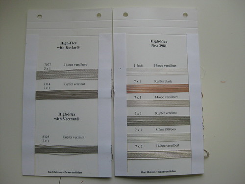
Copper plate non-solderable conductive thread or fabric traces >> http://www.kobakant.at/DIY/?p=2999


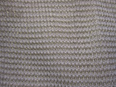
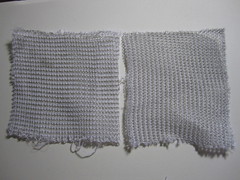
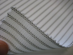
Plug and Wear actually manufactures a fabric breadbaord that is made of alternate conductive and non-conductive knit rows. The conductive rows are knit with a thin flexible wire, and they can easily be soldered to. The spacing of the conductive rows matches that of standard electronics components, which means about three conductive rows per cm. This could be a really nice option, and it can be left up to the person applying the robot skin to their particular project, how much resolution they want and thus whether they connect every conductive row (ca 2 mm resolution) or every other (ca. 5mm resolution). >> http://www.plugandwear.com/default.asp?mod=product&cat_id=89,103&product_id=80

Plug and Wear also sells a flexible perfboard strip >> http://www.plugandwear.com/default.asp?mod=product&cat_id=95,101&product_id=116

I like the idea that you could purchase a tube, cut it to your desired length, solder/rivet/connect to as many rows and columns as you want resolution and connect these to multiplexer modules that carry all the data to a central point. The only thing i don’t like is that you have all these wires sticking out. I see that the robot arm already has some wires running alongside it, so maybe this is not the end of the world. But i also see each wire as a potential problem. With e-textiles in particular, every hard/soft connection presents an opportunity for error. Maybe a third layer of skin could work as a bus line, carrying all the circumference columns along the arm and back to one area. Maybe there would also be a way of embedding the multiplexer right into the fabric, so that each 8×8 matrix section would only need 7 connections (power, ground, COM and A, B, C, D). Though 7 is still a lot for an 8×8 grid, if you might end up having 6 of them to cover your whole arm.
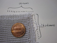
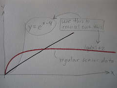
Because of the many contacts that accumulate (one for each row and column), a module approach starts to make sense, where each module (a section of skin) has 16 rows and 16 columns that connect via 16-channel multiplexers to a single microcontroller. To avoid the need for external pullup resistors (one for each multiplexer, which is not that many, but still), i’m looking to find a piezoresistive fabric that will work well in the range of the internal pull-up resistors, which are 10-20K Ohm.
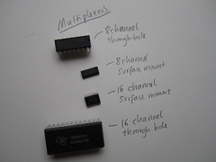
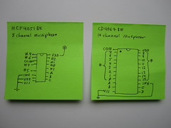
Multiplexers:
The 16 channel multiplexer requires 7 connections to read 16 channels (rows and/or columns of data), these are power, ground, COM and A, B, C, D control pins.
The 8 channel multiplexer requires 6 connections to read 8 channels, these are power, ground, COM and A, B, C control pins.
Toray woven fabric (not solderable)

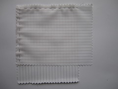
Plug and Wear knit fabric (solderable!)
